Release Date: 07-19, 2024
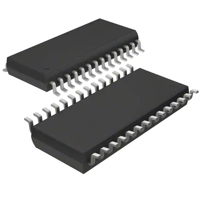
The TSC2200IPWRG4 is a precision analog-to-digital converter (ADC) known for its high accuracy and reliability. However, like any electronic component, it can encounter issues that affect its performance. Understanding common problems and knowing how to troubleshoot them is crucial for maintaining the integrity of your circuits. Here’s a comprehensive guide from ChipGuest on common issues with the TSC2200IPWRG4 and practical solutions to address them.

Problem: The TSC2200IPWRG4 operates within specific voltage ranges. Incorrect voltage levels can cause inaccurate readings or complete failure of the chip.
Solution: Verify that the chip is powered with the correct supply voltage, typically between 3V and 5V, as specified in the datasheet. Use a multimeter to check the actual voltage supplied to the chip and ensure it matches the required levels. Ensure that your power supply is stable and free from significant fluctuations.
Problem: Noise and signal interference can degrade the performance of the ADC, leading to errors in conversion and inaccurate output.
Solution: Implement proper filtering and decoupling techniques to minimize noise. Use bypass capacitors close to the power supply pins to filter out high-frequency noise. Shielding and careful PCB layout can also help reduce electromagnetic interference (EMI). Ensure that analog and digital grounds are properly separated to avoid ground loops and interference.
Problem: Inaccurate conversion results can be caused by several factors, including improper reference voltage or calibration issues.
Solution: Check the reference voltage applied to the ADC. The reference voltage should be stable and precise to ensure accurate conversions. If the chip requires calibration, follow the calibration procedure outlined in the datasheet to adjust the offset and gain settings. Ensure that the reference voltage source is of high quality and free from noise.
Problem: Applying voltages beyond the specified input range can damage the chip and result in incorrect readings.
Solution: Ensure that input voltages are within the acceptable range specified in the datasheet. Implement protection circuits, such as clamping diodes or series resistors, to prevent overvoltage conditions from damaging the chip. Regularly monitor input signals to ensure they stay within safe operating limits.
Problem: The ADC's performance can be affected if the input signal is not sampled correctly or if the sampling rate is too high or too low.
Solution: Adhere to the recommended sampling rate and input signal requirements outlined in the datasheet. Ensure that the signal being sampled is stable and within the chip's bandwidth limits. Use appropriate analog filtering to condition the signal before sampling to avoid aliasing and ensure accurate measurements.
Problem: Excessive heat can affect the performance and reliability of the TSC2200IPWRG4, leading to errors and potential damage.
Solution: Ensure that the chip is operating within its specified temperature range. Provide adequate heat dissipation by using appropriate heatsinks or ensuring proper airflow around the chip. Monitor the operating temperature and take corrective actions if excessive heat is detected.
Problem: Poor PCB design and layout can lead to signal integrity problems, affecting the chip's performance.
Solution: Follow best practices for PCB design, such as minimizing trace lengths, maintaining proper trace impedance, and separating analog and digital signals. Ensure that the layout allows for good signal routing and minimizes crosstalk. Use proper grounding techniques and place decoupling capacitors close to the chip.
Problem: Physical damage to the chip or faulty connections can lead to malfunction or complete failure.
Solution: Inspect the chip and PCB for visible signs of damage, such as cracks or burns. Verify all connections and solder joints to ensure they are secure and free from defects. Replace any damaged components and reflow any problematic solder joints.
The TSC2200IPWRG4 Chip is a highly capable ADC, but like all components, it can encounter issues that impact its performance. By understanding common problems such as incorrect voltage levels, noise and interference, inaccurate conversion results, overloading, improper signal sampling, heat issues, PCB design flaws, and component damage, you can take proactive steps to troubleshoot and resolve these issues. Following the expert tips from ChipGuest will help ensure that your TSC2200IPWRG4 operates reliably, providing accurate and stable analog-to-digital conversion for your applications.